The database is not configured. Add app/config.local.php so the reader can write this table.
No activity yet.
| Time | Action | Who | UID | Result | Code | Latency | Signal | Reader |
|---|
Name a card
Tap first. Click a UID in the table, give it a person, save. The next tap of that card shows green.
Reader token
Lights
- Green — recognized
- Solid red — blocked
- Orange flash — unrecognized
- Red flash — error
- Blue flash — Wi-Fi
- Dim white swirl — waiting
3-pin buzzer: S → GPIO25, + → 5V (louder) or 3V3, − → GND. Recognized: two rising beeps. Unrecognized: one lower beep. Blocked: two falling beeps. Error: three mid beeps. Waiting is silent.
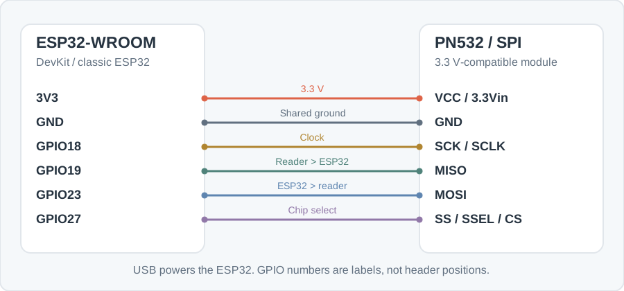
SPI wiring
Power off before moving wires or flipping mode switches. The PN532 is 3.3 V only. Use GPIO numbers, not the physical pin count from USB.
| ESP32 | PN532 |
|---|---|
| 3V3 | VCC / 3.3Vin |
| GND | GND |
| GPIO18 | SCK / SCLK |
| GPIO19 | MISO |
| GPIO23 | MOSI |
| GPIO27 | SS / SSEL / CS |
| ESP32 | Buzzer module |
|---|---|
| GPIO25 | S (signal) |
| 5V | + / VCC |
| GND | − / GND |
On a common ELECHOUSE-style V3 board, SPI is switch 1 OFF and switch 2 ON. Confirm the printed table on your module. IRQ and RST are unused. LED data is GPIO26; the first 12 pixels light. Power the strip from a separate 5 V supply and join grounds. The buzzer is a 3-pin module: S to GPIO25, + to the ESP32 5V pin for volume, − to GND. Do not put 5 V on S. Power off before wiring.
The reader posts every tap to . Heartbeats keep the reader online without adding table rows.